




For water supply and pumping systems, specifying an AWWA C508 Check Valve provides an important technical baseline, but the standard designation alone does not describe everything that will determine how the valve behaves after installation. A check valve has to prevent reverse flow, but it also interacts with changing velocity, pump shutdown, pressure fluctuations, solids in the water, and the hydraulic characteristics of the surrounding pipeline.
The current AWWA C508-25 standard covers iron-body swing-check valves for waterworks service and defines the general scope and minimum requirements for this valve category. However, AWWA also notes that the standard is intentionally silent on some assisted-closure design details. This distinction matters: two valves may both be specified to AWWA C508 while using different disc arrangements, closure-assistance mechanisms, sealing concepts, and maintenance structures.
For engineering projects, the useful question is therefore not simply whether the nameplate says “AWWA C508.” It is whether the complete valve design fits the hydraulic behavior, connection conditions, and maintenance strategy of the actual pipeline.
What Does AWWA C508 Tell You—and What Does It Not Tell You?
AWWA standards provide common technical requirements that help create a shared basis for waterworks products. The latest AWWA C508 standard is specifically for swing-check valves used in waterworks service, including source water, potable water, wastewater, and reclaimed water applications within its stated scope.
That standard reference is valuable because it gives a project team a recognized framework. But it should not be treated as a complete description of every valve characteristic. In practice, a project still needs to understand how the valve opens, how quickly it responds when forward flow decays, how the disc returns toward the seat, what sealing system is used, and how much resistance the open valve introduces into the pipeline.
This is particularly important for check valves because their operation is not controlled manually under normal service. Their movement is driven by changing flow and pressure conditions. A valve can meet a dimensional or pressure requirement and still respond differently from another design during pump shutdown or rapidly changing flow.
Why Closing Behavior Matters as Much as Backflow Prevention
The simplest description of a check valve is that it allows forward flow and prevents reverse flow. In real pumping systems, however, the transition between those two conditions determines much of the valve’s dynamic behavior.
When a pump stops, forward velocity decreases rather than disappearing instantaneously. If the valve disc remains open until substantial reverse velocity has developed, the eventual closure can create a stronger mechanical and hydraulic event. The resulting transient depends on far more than the check valve alone; pipeline length, wave speed, pump inertia, static head, and system layout all influence the final pressure response.
This is why “fast closing” should not be interpreted as “the faster the better.” A better objective is timely closure before excessive reverse velocity develops, combined with a closing motion that does not introduce unnecessary mechanical impact.
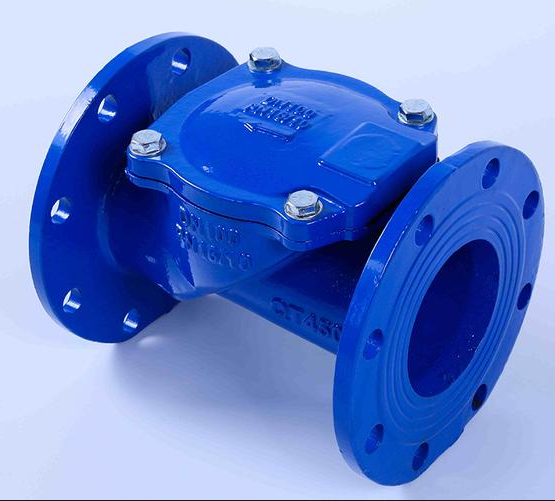
RMT’s individual AWWA C508 product uses a 45° rubber disc arrangement together with a stainless-steel spring plate accelerator intended to follow disc movement and accelerate closure. That is a specific design feature beyond the standard name itself and is relevant when evaluating how the valve responds to changing flow.
Why a 45° Rubber Disc Changes the Closing Process
A 45° rubber plate check valve does not behave exactly like a conventional long-travel swing check valve. The geometry reduces the disc travel required between the open and closed positions, while the resilient disc provides the sealing interface.
A shorter travel distance can be important because check-valve closure is a race between two processes: the disc returning to its seat and the pipeline flow decelerating toward reversal. If the disc has less distance to travel and receives closure assistance, it may reach the seat earlier in that transition.
However, the real performance still depends on actual operating conditions. Flow velocity, pressure differential, installation orientation, and upstream disturbances can all change the force acting on the disc. Therefore, the 45° structure should be understood as a way of influencing valve response rather than as a guarantee that water hammer will disappear from every system.
For long pipelines or high-energy pumping systems, surge analysis may still be necessary because no single check valve can eliminate all transient pressure effects created by the complete hydraulic system.
Why Full-Port Flow Area Matters During Normal Operation
Check valves spend most of their operating time open, so normal-flow resistance deserves as much attention as closure behavior. A valve that protects the pipeline during shutdown but creates excessive head loss during every hour of operation can increase pumping energy requirements.
The hydraulic relationship can be understood through the basic continuity equation:
Q = A × V
where Q is flow rate, A is effective flow area, and V is average velocity. If the internal flow passage becomes restricted, local velocity rises and additional losses can develop around the restriction.
RMT’s AWWA C508 product page describes the valve as a full-port design with a non-restrictive flow path intended to reduce head loss and allow larger solids to pass with less risk of blockage.
For water and wastewater applications, this has two practical implications. First, lower unnecessary restriction can help reduce continuous pumping losses. Second, a less obstructed passage may be useful in systems where debris or larger suspended material could otherwise accumulate around a narrow internal geometry.
Why Sealing Performance Should Be Considered Across Different Pressures
A check valve does not always close under the same differential pressure. System conditions may vary during normal operation, pump shutdown, commissioning, or low-flow periods. The sealing mechanism therefore needs to remain effective across the intended operating range.
RMT’s product uses a synthetic reinforced rubber disc and an integral V-type sealing arrangement, which the company describes as providing sealing at both high and low pressures. The valve body and cover are ductile iron, while the sealing components include EPDM.
The engineering value here is not simply “rubber seals better.” Resilient sealing allows controlled deformation at the contact interface, helping maintain sealing contact when small surface variations exist. At the same time, the elastomer needs to remain compatible with the medium and service temperature, so the material should always be considered together with actual pipeline conditions.
Maintainability Can Matter Years After the Valve Is Installed
Check-valve articles often focus heavily on flow and pressure but ignore a practical question: what happens when the internal disc eventually requires inspection or replacement?
Removing an entire check valve from a pipeline can require isolation, lifting equipment, flange disassembly, and significant downtime. For larger valves or fixed installations, access to internal parts can therefore affect lifecycle maintenance cost.
The RMT 45° Rubber Plate Check Valve uses an arched top cover designed to provide access to the rubber disc without removing the valve body from the pipeline. The product page also notes space for flushing around the disc area and an optional tapped location for a disc-position indicator.
This type of maintainability feature does not change the basic function of the valve, but it can change how difficult the valve is to inspect or service after years of operation. For infrastructure systems expected to remain in service for decades, that is worth considering during the original project design rather than only after a maintenance problem appears.
Why Connection Details Still Need to Be Confirmed
AWWA C508 compliance does not mean every project interface is automatically identical. Flange standard, nominal size, pressure rating, installation length, and project-specific requirements still need to match the surrounding pipeline.
RMT’s current product page lists its 45° Rubber Plate Check Valve in DN50–DN300, PN10 and PN16 configurations, with EN1092.2 flange connections and water as the stated applicable medium. The page also identifies AWWA C508 as the design standard.
This combination illustrates why the standard designation should be only one part of project confirmation. Before production, the valve specification should be checked against the actual flange interface, pipeline pressure, system layout, and intended operating conditions.
RMT AWWA C508 Check Valve Solution
RMT provides an AWWA C508 Check Valve solution based on its 45° Rubber Plate Check Valve design. The product combines a full-port flow path, reinforced rubber disc, spring-assisted closing arrangement, resilient V-type sealing, and a removable top-cover design intended to support both hydraulic performance and later maintenance.
For water supply, pumping, and related pipeline projects, RMT can support the project from technical confirmation through production and delivery. Instead of treating AWWA C508 as the only requirement, the valve can be discussed together with actual pipe size, working pressure, flange connection, flow conditions, installation environment, and project quantity.
If your project requires an AWWA C508 Check Valve, send RMT the valve size, working pressure, flange standard, application conditions, and required quantity. These details allow the technical team to review the connection and operating requirements before production and recommend a valve configuration that better matches the pipeline.
FAQ
1. Does AWWA C508 compliance mean all check valves have the same structure?
No. AWWA C508 establishes requirements for the covered valve category, but individual manufacturers may use different disc, sealing, and closure-assistance arrangements. The specific valve design should still be reviewed for the intended system.
2. Can an AWWA C508 Check Valve eliminate water hammer?
Not by itself. Check-valve closing behavior can influence transient pressure, but water hammer also depends on pump behavior, pipeline length, fluid velocity, system head, and other hydraulic conditions.
3. Why is a full-port design useful in a check valve?
A less restrictive internal passage can reduce unnecessary head loss during normal operation and may provide better passage for suspended solids compared with a more restricted flow path.
4. What information should be provided for an AWWA C508 Check Valve project?
Useful project information includes nominal valve size, working pressure, flange standard, medium, installation conditions, expected flow conditions, and required quantity. Providing these details early helps confirm compatibility before manufacturing.
Conclusion
An AWWA C508 Check Valve should not be judged only by the standard printed in the specification. The standard provides an important technical foundation, but actual pipeline performance also depends on closing behavior, flow passage, sealing design, maintenance access, and system conditions.
For projects that need a 45° rubber plate check valve solution, RMT combines AWWA C508-based design requirements with a short-travel rubber disc, spring-assisted closure, full-port flow path, and serviceable top-cover arrangement.
Have an AWWA C508 Check Valve project? Send RMT your pipeline requirements, and the team can help confirm the suitable valve configuration and connection details before production.
Post time: Sep-12-2026